
For generators rated above 1 MVA, it is common to apply generator differential protection for stator phase faults. This form of unit protection allows discriminative detection of winding faults, with no intentional time delay, where a significant fault current arises.
Circulating current differential protection operates on the principle that current entering and leaving a zone of protection will be equal. Any difference between these currents is indicative of a fault being present in the zone. CTs are connected as shown in below figure:
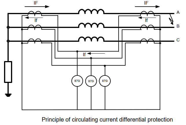
It can be seen that current flowing through the generator windings will cause current to circulate around the secondary wiring. If the CTs are of the same ratio and have identical magnetizing characteristics, they will produce identical secondary currents and hence zero current will flow through the relay. If a fault exists inside the windings, there will be a difference between the outputs from each CT. This difference will be flowing through the relay causing it to operate.
A) Biased Differential Protection
In a biased differential relay, the through current is used to increase the setting of the differential element. For heavy through faults, it is unlikely that the CT outputs at each zone end will be identical, due to the effects of CT saturation. In this case a differential current can be produced. However, the biasing will increase the relay setting, such that the differential spill current is insufficient to operate the relay.
For numerical relays, the differential and bias currents are derived by algorithmic calculation, after measurement of the individual CT secondary currents. The relay design will normally have full galvanic separation of the neutral-tail and terminal CT secondary circuits. There are two different solutions to calculate the differential and the bias currents, as shown in below figure:
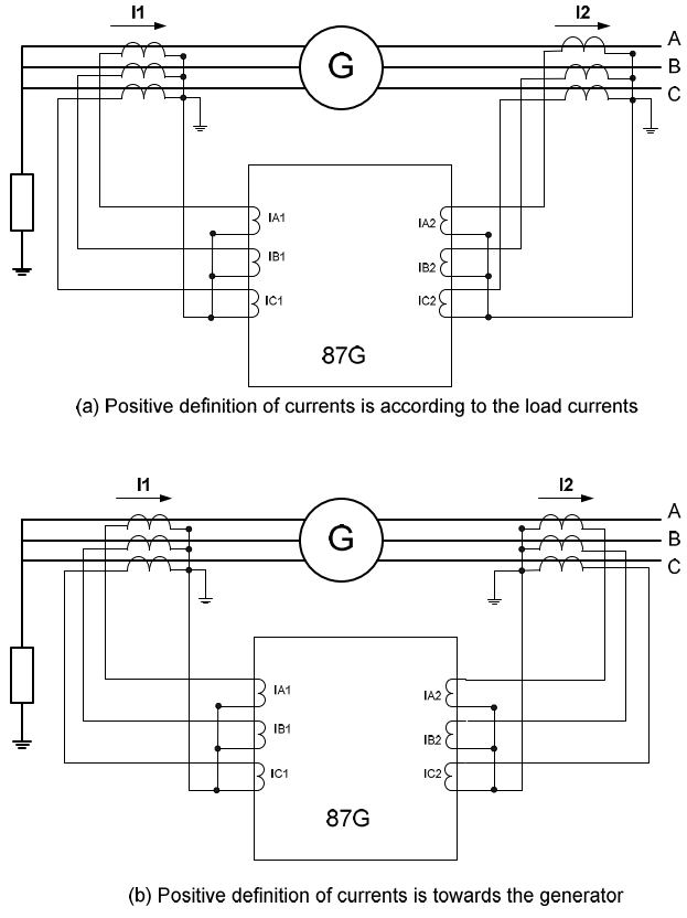
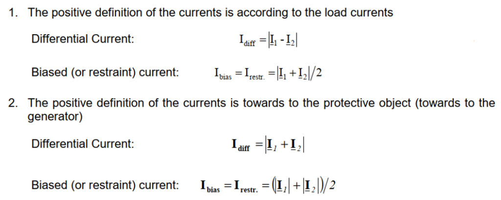
In both cases the calculation of the differential current is the same. The sign (- or +) is determined by the positive definition of the currents. The main difference is in the calculation of bias current and which leads to different operating ranges in the characteristic. From the user’s point of view, the major consideration is in the selection of parameters for the characteristic, mainly the inclination of the straight line.
A typical duel-slope operating characteristic of a biased differential protection is shown in below figure.
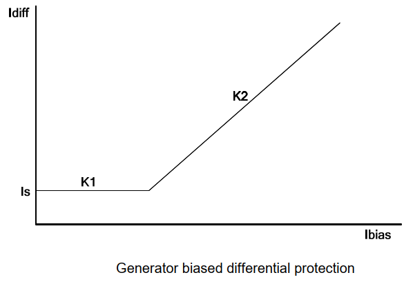
For general applications, the differential current threshold setting Is can be set as low as 5% of the rated generator current, to provide protection for as much of the winding as possible. The K1 slope would typically be set to 0% in order to maintain protection sensitivity irrespective of the generator loading condition. This sensitive setting is only allowed if the current transformers are well designed i.e., same types on both sides and good transient behaviour even in the case of small fault currents with large DC time constants. The bias slope break-point threshold setting Is2 would be set to a value above the generator rated current, say 120%, to achieve external fault stability in case of transient asymmetric CT
saturation. Bias slope K2 would typically be set at 15-20%.
The threshold setting can be raised for applications where a relatively small unit auxiliary transformer or excitation supply transformer is teed-off within the zone of differential protection. In such cases, the differential setting should be set so as to prevent operation for faults on the LV side of the transformer, or to grade the differential protection’s operating time with the transformer fuse protection.
The protection should have additional counter measures to avoid mal-operation during external faults or during switching on of an external load with large time constants, e.g., a transformer. The main problem is the transient behaviour of the CT. There are two worst-case situations:
1) External short circuit with a large fault current and a full DC offset
In this case, if one CT saturates a large differential current will be produced and it can reach into the tripping zone. Therefore a CT saturation detector is required to avoid mal-operation.
2) External short circuit with small fault currents or additional load current during switching on a large load.
In both cases it is assumed that there is a full DC offset. The large load can be for example the inrush current of a transformer, which is switched on. In this case, there is no typical CT saturation, but a phase shifting is possible, which leads to a small differential current. Since the differential and the bias currents are in the sensitive point of the characteristic (the low slope K1 region in figure), with a sensitive setting a trip is possible. Some manufacturers design their protection so that it will detect such kind of “quasi saturation” and block the trip.
B) High Impedance Differential Protection
The high impedance principle is best explained by considering a differential scheme where one CT is saturated for an external fault, as shown in below figure:
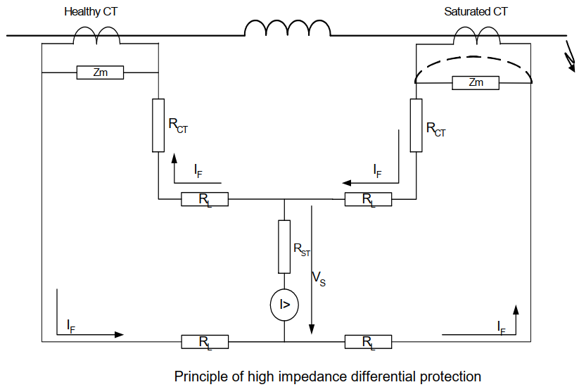
If the relay circuit is considered to be very high impedance, the secondary current produced by the healthy CT will flow through the saturated CT. If the magnetizing impedance of the saturated CT is negligible, the maximum voltage Vs across the relay circuit will be equal to the maximum secondary fault current IF multiplied by the connected impedance, (2RL + RCT), where RL is the lead resistance and RCT is the current transformer secondary winding resistance.
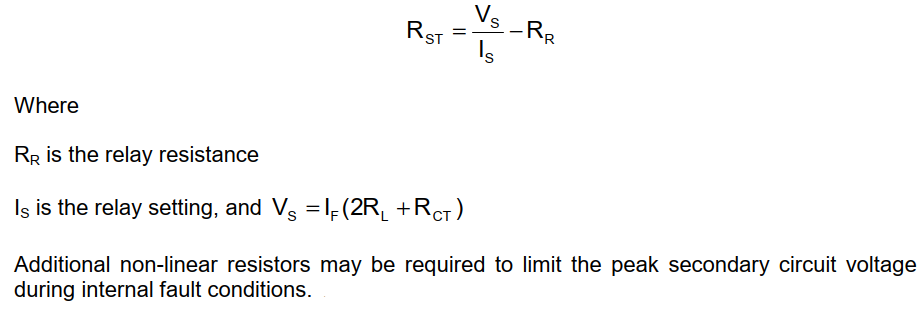
The relay can be made stable for this maximum applied voltage by increasing the overall impedance of the relay circuit, such that the resulting current through the relay is less than its current setting. As the impedance of the relay input alone is relatively low, a series connected external resistor is required. The value of this resistor, RST, is calculated by the formula as shown.
The connection arrangement is as shown in below figure:
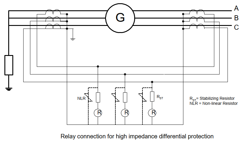
The high impedance differential protection has the characteristics of maintaining a constant sensitivity with varying load current and in being able to use smaller CTs. The latter can provide advantages over the biased differential protection, especially for retrofit applications.
C) Self Balancing Differential Protection
For small generators where the neutral and line end connections of the phase windings are separately available, a core balance (or window) type CT can be mounted around the connections of each phase winding, as shown in below figure. Under normal conditions, no current will flow on the CT secondary because of zero flux. Therefore the CT ratio can be low and there is no need to consider the nominal current of the generator.
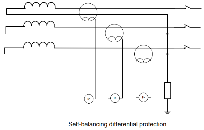
A simple instantaneous overcurrent relay can be connected to the secondary of the CT to measure the difference in the current entering and leaving the phase winding. Sensitive protection of phase and ground faults can thus be achieved.
The small CT window limits the size of the conductor and hence the size of the generator that can be protected. The relay should be of the low burden type to reduce the possibility of CT saturation for internal faults.
Relevant Online Courses
- https://powdemy.org/courses/protection-and-control-of-high-voltage-power-circuits/
- https://powdemy.org/courses/detailed-course-on-rotating-machines-ac-and-dc-motors-and-generators/
- https://powdemy.org/courses/etap-power-system-protection-analysis-beginner-to-advanced-level/
- https://powdemy.org/courses/complete-etap-power-system-analysis-for-electrical-engineers/
- https://powdemy.org/courses/electrical-power-system-stability-beginner-to-advanced-level/